Rebar Bending
Line Model: BL32 / BL40
Available in Two Models – To Suit Maximum Size TMT Bar METRIC32 (BL-32) And METRIC40
(BL-40)
WE ARE OPEN AND FUNCTIONING! WE HAVE STOCKS OF SEVERAL MODELS TO MAKE IMMEDIATE DOMESTIC DISPATCHES AND OVERSEAS SHIPMENTS. PLEASE CONTACT US FOR A QUOTE.
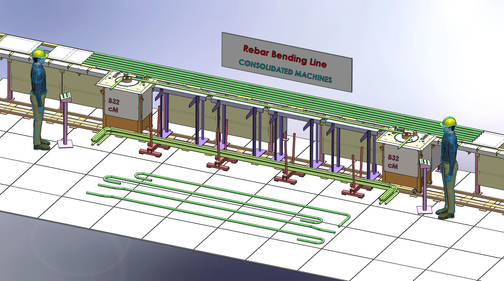 Arrangement for Both End Simultaneous Forming
Rebar Bending Line Model: BL32 / BL40
General Features
✓ Available in Two Models –
To Suit Maximum Size TMT Bar METRIC32 (BL-32) AND METRIC40 (BL-40)
Machines with Electric Control or with PLC Control (Discussed Later)
Arrange the Plant for: Both Ends Simultaneous Bending or One Side Bending Illustrated in Pictures
Production Estimate per Ten Hour Indicative: Model BL32 35 TONS Model BL40 50 TONS
Plant Foot Print: 14M X 3M
Machines Move on Rails – Effortless Accurate Positioning and Lock Position with Push Button Track Rail Length 14M
Modular Construction – Easy to Install or Relocate
Bending Machines
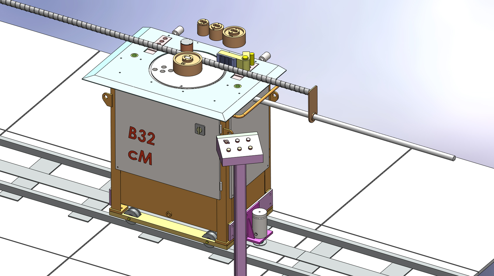 Bar Bending Machine for Bending Line Application
In General, the Bending Machine Design Is More Elaborate to Suit Such Bending Line
Application
✓ Boosted Bending Speed – Higher Power Installed
✓ Machine Design Facilitates Simultaneous Bending on Both Machines Inline
✓ Bend Table and Tooling to Suit Proper Is1786 Specs
✓ Wheels and Brakes Incorporated to Move the Machine on Track Rails and Lock Position
Electro-Hydraulic Drive
✓ Built with Best in Class Elements like Bosch Rexroth / Yuken / Siemens
Bi-Directional Bending Capable
bending Speed near Five RPM
Tooling Specs : Mandrels and Bending Table to Suit IS1786 Specs For Bar Grades FE500 / FE550D.
Bending Capacity Metric TMT Grade FE500 / FE550D (BAR SIZE X NO OF BARS)
MODEL BL32: 32X1 25X1 20X2 16X3 - Lap Joint Forming Max Bar Size 20
MODEL BL40: 40 / 32X1 25X2 20X3 16X4 Lap Joint Forming Max Bar Size 25
Power Installed: Standard Three Phase Ac Motors – On Each Machine
MODEL BL32 : 5HP (3.8KW)
MODEL BL40 : 7.5HP (5.8KW)
(Brakes Are Air-Operated. 1HP X 6BAR Air-Compressor Be Installed by the User)
Bending Accuracies
Angle Setting Resolution 3 Deg – Means Target Value Deviation Max +/- 1.5DEG Which Is within the Acceptable Deviation Limits
Optional PLC Controlled Machines
Angle Setting Resolution 1 DEG – Means Target Value Deviation Max +/- 0.5 DEG Note That Repeat Accuracy Depends on Fine Machine Setting and Rebar Material Elasticity.
Forming Limitation for Both End Forming
Minimum Distance of Bending Heads – 1.2 M
Maximum Distance of Bending Heads – 11.5 M
Bar Support System
1. Bar Receiving Pedestal - Pedestal Length 12M – Maximum Weight Capable 4T Distributed
2. Intermediate Bar Support – This Arrangement Is Integrated with Main Pedestals.
Activate
The Segment as Required – Picture Illustrated Or Optional Bar Kick-In Kick-Out
Modules – Six Units
3. Bar Position Reference Flags
4. Formed Bars Collecting Elements – Eight Numbers – Arranged as Required
Materials and Finish
Tooling and Load Bearing Elements of Alloy Steel Toughened, Phosphate Finish Panels Powder Coated, Structure Fabrication with Zinc Red-Oxide and Quality Paint Finish
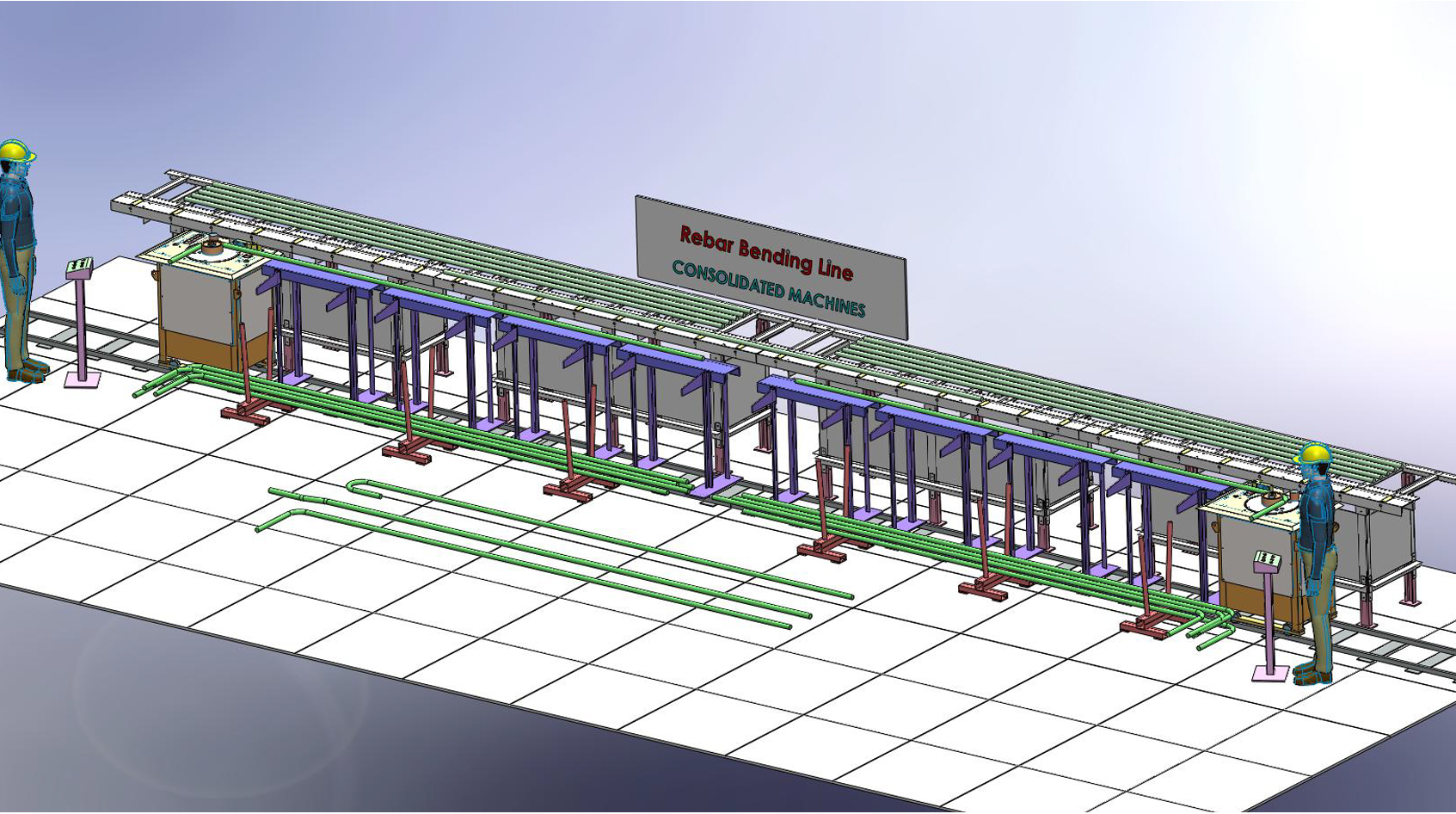 Arrangement for One End Forming – Both Machines Utilized
Plant Setup and Production
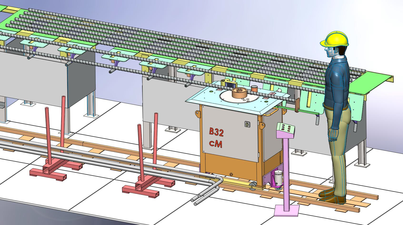 Plant Setup – Refer following Notes
Setup : A near Ten-Minute Process
1. Suitable Mandrel Rollers Are Installed on the Machine Bending Head
2. Both Machines Are Positioned as Required and Locked (Length Setting)
3. the in-Between Bar Support Elements Are Activated
4. the Bar Linear Position Reference Flag Is Set
5. Formed Bar Collecting Bin Elements Are Adequately Positioned
Plant Is Now Ready for Production
1. Operator Rolls the Bar to Drop onto the Bending Table, Tangent to the Bending Roller
2. Bar Position Reference Flag Is Activated and the Bar Is Positioned, Flag Is Then Deactivated
3. Bending Is Activated - Bend Angle Is Achieved as per the Setting
4. Bending Table Returns to Home Position
5. Bar Is Disengaged from the Center and Pushed off the Table to Drop into the Collecting Bin.
6. Next Bar Is Rolled into the Position and Process Continues
Cycle Time Less than a Minute
Optional Features: Bar Kick-In / Kick-Out
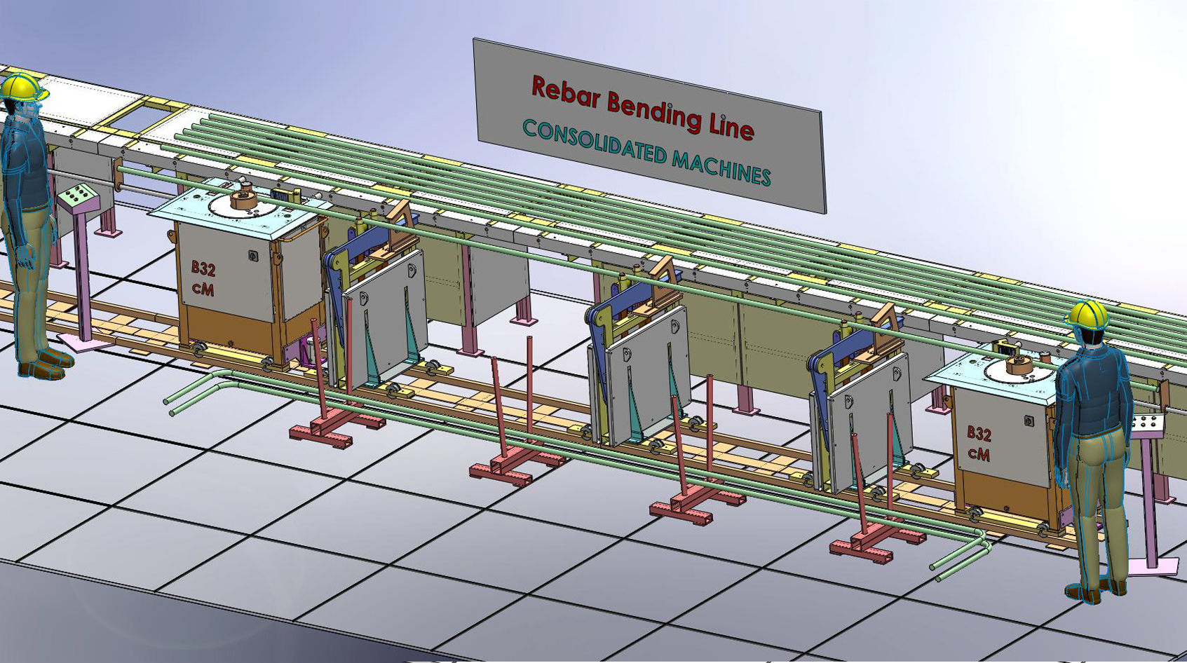 Arrangement with Bars Kick-In Kick-Out System
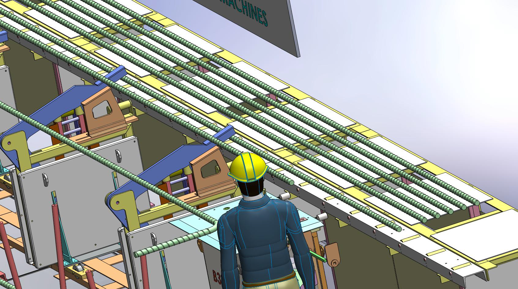 Closeup View of Kick-In Kick-Out System - In Action
▪ Kick-In / Kick-Out Six Modules Are Provided
▪ Modules Are Supported on the Common Track Rail – Position the Modules as Required
▪ Modules Are Air-Operated – User Will Provide Compressed Air Facility. a Common Air Compressor 5HP (10 TO 12 CFM AT 8 BAR) would Be Sufficient
▪ Working – the Incoming Bar Is Rolled onto the Pads. When Operated (With a Push Button) the Formed Bar Is Kicked-Out into the Bin and the Fresh Bar Is Loaded onto the Bending Table.
Caution
▪ Bars Kicked-In Will Be in Straight Form Only
▪ Some Critically Formed Bars like U-Bend May Resist a Kick-Out Action, Operators Support May Be Required
▪ Carefully Evaluate Optional Features Later Upgrades May Be Difficult
Notes on Plant Installation
▪ The Plant Foot Print Floor Area Must Be Good Quality Industrial Flooring
▪ Track Rails Required to Be Mildly Grouted, Detail Drawings Will Be Furnished
▪ The User Will Accomplish This as a Part of Civil Work
▪ Pedestals Are Supplied in Modular Form, Assembly Instructions Will Be Furnished, Pedestals Are Free-Standing
▪ Machines Are Supplied in Fully Assembled State
▪ Kick Modules (Optional) and Bin Elements Are Arranged as Required.
DROP US A LINE
Phone:
Hoshang Jhabvala
: +91 98200 77035
Rayomand Jhabvala : +91 98200 79035
Asad Adeni : +91 92465
68775
© Copyright 2020 Consolidated Machines - Designed and Maintained by Upshot Media
Whatsapp Button
Click the "gear" icon to change the layout of the Whatsapp Button. This text will be removed on preview/publish.
Floating Social Menu and Ribbons
Click the "gear" icon to change the layout of the social bar. This text will be removed on preview/publish.